Measurement and Control of Drift in the Surface Forces Apparatus
This page presents possible sources of drift in the Surface Forces Apparatus (SFA). We present long-term drift measurements which illustrate the extent and properties of different sources of drift in the SFA. Furthermore, we discuss possible countermeasures to reduce drift. The following list contains potential sources of drift in the SFA. Underlined items are being discussed in more detail below.
Potential Sources of Drift in the SFA
- Thermal drift due to temperature variations in and around the SFA.
- Instrumental drift due to interfacial settlement of moving parts (e.g. actuator).
- Systematic drift due to tidal forces (moon, sun)
- Drift induced by dynamics of surface forces (evaporating meniscus, relaxing film...).
- Instrumental drift due to face seal of functional attachment.
- Instrumental drift due to cold flow of SFA parts under stress.
- Drift due to faulty parts and joints.
Thermal Drift
Every material has a thermal expansion, so do the parts, which the SFA mechanical loop is made of. In practice, this translates into a variation of the surface separation, D(T), as a function of the temperature, T, around the SFA. Every material has also a thermal capacity that determines how fast a part will warm up (thermal inertia, time constants). Furthermore, the interface between parts may represent a difficult-to-control barrier for heat transfer.
It is possible to measure the thermal expansion of an SFA. Therefore, we have stabilized the SFA temperature to ±2mK (for about 8 hours) before we induced a temperature step of +5.00°K. The resulting measurement of surface separation, D(t), as a function of time, t, reveals thermal expansion and the relevant time constants. We have also conducted experimenta with temperature steps of -5°K and ±10°K, which are consistent with the ones presented in the following Figure 1.
Figure 1: Thermal expansion of the Surface Forces Apparatus with different functional attachments - piezo device (PD) and friction device (FD).
From Figure 1, we can quantify the thermal expansion to be 100nm/°K for the piezo device and -350nm/°K for the friction device. This difference mainly stems from the large thermal expansion of the piezo ceramic (PD). Moreover, it becomes clear that a temperature control with a stability of a few mK is needed to suppress thermal drift effectively.
We have built a temperature control which complies with these specifications.
Interfacial Settlement
Many metals are covered by a passivating oxide layer of varying thickness. When such parts are brought into mechanical contact, the oxide layer may change its thickness in the contact zone. Furthermore, when two different metals are brought into contact, a chemical reaction may occur, which further changes the interfacial structure over time. Similar effects may occur when the surface of parts is covered by contaminations or viscous lubricant. Generally, interfacial settlement may occur over a wide range of time scales.
In the SFA, interfacial settlement plays an important role whenever new interfaces between parts are formed. That is essentially the case on two occasions: Namely, when the SFA is assembled before a measurement, or, when parts are moved during the measurement (micrometer, motor...).
Tideal Forces
Due to the geometric size of earth, centrifugal and gravitational forces do not exactly cancel out on the surface of our planet. The total (sun and moon) tideal force is a vector and the SFA is principally sensitive to the normal component of that force. Calculations show however that these forces result in a nominal spring deflection (k=100N/m) in the picometer range. These small amplitudes, which have a 24 hours cycle are thus generally negligible for practical purposes.
Face Seal
Modern SFAs allow to use different attachments to add functionality. A good example is a functional attachment that allows measurement of lateral forces (friction). One of the two surfaces is generally fixed to the functional attachment. The functional attachment is usually sealed to the SFA main chamber by a face seal. The face seal is typically realized by a flansh which is pressed against an O-ring as shown in the figure below.
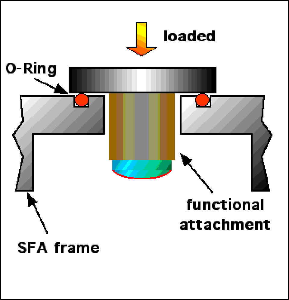
It appears that the material and geometry of the O-Ring plays a decisive role determining the amount of drift that can emerge from this design. A first important question is whether the O-Ring is cussioning the face seal or the flansh is pressed all the way down to the SFA frame to form a rigid contact. The first case of these two is especially detrimental since, stress relaxation and plastic flow of the visco-elastic O-Ring will directly translate into instrumental drift. The distance drifted by plastic O-Ring deformation can easily be in the order of a few ten micrometers and is essentially limited by the stiffness of the loading mechanism. In the simplest case, the loading mechanism consists of two or more screws, which bolt the flansh of the functional attachment to the SFA frame. These screws have a relatively high stiffness, so that a relaxation of the O-Ring leads to a release of the load - a process that can go on for weeks! We have measured instrumental drift in our SFA with and without protruding (cussioning) O-Ring and illustrate these results in figure 3.
Figure 3: Measurement of instrumental drift due to O-Ring deformation in the face seal..